


How to Build the Arm
Table
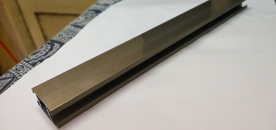
The arm is made of two aluminium channels, 30cm long (centre to centre distance) which act as base and elbow. This assembly rests on a wooden block (16cm * 10cm * 8cm), which is further attached to a
plywood (60cm * 60cm).

Base Channel
One end of the base channel is attached to the wooden block through a gear-ball bearing assembly. The assembly also contains a 3D printed part, which connects the gear and the ball bearing. The ball bearing is attached to a metal rod which is fixed to the wooden block. The 3D printed part is above the bearing and the gear is placed above the 3D printed part. A 180 degree servo, placed over wooden block, is used to control the movement of base channel through the gear.

Elbow Channel
The elbow channel is attached to the other end of base channel, again through a gear-ball bearing assembly. This assembly too contains a 3D printed part which does the same job. A 180 degree servo, attached to base channel, is used control the motion of elbow channel through the gear.
The robotic arm should be very precise so that it can pick up pieces and place them at accurate positions. We faced many problems while using servos available in market (especially the clones of TowerPro MG995), so we recommend you to buy servos online through Robokits. The component list, given below, has all the details about the components that we have used and also about the 3D printed parts.